Smart Ass Fuel Mule Gas Caddy with Pump - User Manual
![]()
Smart Ass Fuel Mule™ 810001A - User Manual [20240531]
It's the Ultimate Gas Caddy: Welcome to the Smart Ass Revolution!!!
Congratulations on your new Smart Ass Fuel Mule™ purchase! We are pleased to help you with your refueling needs and excited to be manufacturing the best gas caddy on the planet right here in the USA, providing a safe and easy to use fuel caddy solution available!
Before using your Smart Ass Fuel Mule™, please read this user manual thoroughly in it’s entirety for best practices and safe handling of the Smart Ass Fuel Mule™ Gas Caddy with pump. Your ability to use this product safely and efficiently will rely heavily on your taking the time to thoroughly understand this manual!
Have questions? Many will likely be covered our FAQ (frequently asked questions)! Don’t hesitate to reach out to us if the FAQ doesn't cover your question! Feel free to email us directly at Info@smartassproducts.net or call us at 404-955-7622.

Table of Contents
Section 1: General Info Section 2: Safety Information Section 3: Product Details Section 4: How To Operate- Driving Procedure
- Loading Procedure
- Unloading Procedure
- Charging procedure
- Charging Location
- Fuel Filling Procedure
- Fuel Dispensing Procedure
- Driving Best Practices
- Fueling Best Practices
- Charging Best Practices
- Loading & Unloading Best Practices
- Storing Conditions
- Emergency Procedures
Section 1: General Info
The purpose of this user manual is to outline all the aspects of owning and operating the Smart Ass Fuel Mule™ for a safe and effective user experience. This user manual covers the following product models:
a. Smart Ass Fuel Mule™ - 810001A - Motorized 50 gallon Gas Caddy, with 15gal/min pump.
Ensure the product description listed above matches the product you have purchased and received. If it does not, please reach out to the Smart Ass Products Team at info@smartassproducts.net and we will address this and ensure you have the correct user manual for your product.
Throughout this document the Smart Ass Fuel Mule™ may be referred to as “Product”. For any questions regarding the Product or this User Manual, please reach out to us directly at Info@smartassproducts.net .
Section 2: Safety Information
DANGERS, WARNINGS, and CAUTIONS
The safety and wellbeing of the operator and bystanders is top priority. This section outlines critical safety information to know, understand, and utilize before attempting to operate the product. As stated in OSHA guidelines, “DANGER means if the danger is not avoided, it will cause death or serious injury. WARNING means if the warning is not heeded, it can cause death or serious injury. CAUTION means if the precaution is not taken, it may cause minor or moderate injury”. These definitions help measure the potential risk associated with the safety labels outlined in this section and also located on your Smart Ass Fuel Mule™ Gas Caddy.
DANGERS
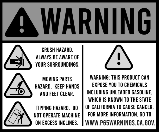
Dangers pose the highest level of risk which can result in injury or death if not addressed accordingly. These dangers should be taken seriously, understood, and accounted for properly by all operators and bystanders of the Product. Not using precaution with these outlined dangers may result in serious injury or death. See Figure 1.

|
Figure 1 |
This off-road capable fuel caddy may contain, transport, dispense and or work around flammable material including but not limited to Gasoline, Gas/Ethanol mixes, Diesel, Biodiesel, Kerosene, AVGAS, Jet A, etc. The operator should take extreme caution in this environment when working with or near your Gas Caddy with Pump to ensure this danger is accounted for.
When dispensing Fuel, the drive motor will be deactivated when you put the keyswitch into the Pump position. All other nearby equipment, engines, and or motors should be powered off prior to dispensing fuel. This reduces the chances of potential ignition sources coming in contact with the fuel vapors from the contents of the Product.
Smoking is prohibited when operating or being in the vicinity of the Product. This includes the operator or bystander. Flammable fumes or liquids can be ignited by a source such as a cigarette or similar. Prohibited activities include but are not limited to smoking cigarettes, cigars, e-cigs, electronic smoking devices, or any other form of smoking.
Open flames of any kind are prohibited in the vicinity of the Product. The operator must ensure the operating environment is free and clear from any open flames or potential open flames. This includes but is not limited to fires, candles, torches, matches, lighters, smokers, barbeques, Oompa Loompas with a steel and flint, fireplaces, and any other potential source of ignition, heat, flame, or sparks.
No person(s) under the age of 16 should operate the Product at any time. This is a nationally recognized best practice for commercial fueling at a commercial fuel pump and should be followed when operating the Product as well.
Power off all cell phones, handhelds, and/or other electronics devices before handling any part of the fuel system.
No vaping, e-cigs, or other electronic smoking devices are allowed when near the Product.
Discharge your static electricity before using any part of the fuel system. This process can be done by first ensuring the Product does not have any fuel or flammable substance on the surface due to spill or overfill, by touching any exposed metal part of the Smart Ass Fuel Mule™ Gas Caddy with Pump (away from the fuel filler and nozzle) with your bare hands and then also touching any exposed metal part of the vehicle being filled (again, away from any area likely to be in the presence of fuel vapor). This discharges the potential static charge you may be carrying reducing the possibility of a static charge that may cause a spark source.
Dangers pose the highest risk of injury if not adhered to may result in serious injury or death. Accommodate for these risks at all times and follow all the rules outlined in this user manual.
WARNINGS
Warnings are less extreme than Dangers but still pose a rather high level of risk that may result in serious injury or death. These warnings should be taken seriously, understood, and accounted for properly by all operators and bystanders of the Product. Not using caution with these warnings may result in serious injury or death. See Figure 2.
|
Figure 2 |
Operation of the Product can result in a possible Crushing Hazard. Operators must read this user manual fully to learn how to control, operate, and safely handle the machine to prevent the potential crushing hazard of the operator or others. Always be aware of your surroundings when operating the Product to prevent a possible crushing hazard.
The Product contains moving parts such as a chain, sprocket, and driven wheels. It is the operator’s responsibility to ensure that the operator and bystanders are staying clear of the Product keeping body parts and objects on their person away from getting close to these moving parts to prevent injury.
Operating this product in certain terrain or conditions may present a tipping hazard. It is the Operators responsibility to only operate the Product within the Products limitations set forth in this user manual. Please refer to section “Operating Conditions” section for the specifics on the limitations of the product to prevent mitigate the tipping hazard.
WARNING: This product can expose you to chemicals including unleaded Gasoline, which is known to the State of California to cause cancer. For more information, go to www.P65Warnings.ca.gov .
Warnings still pose a risk of injury or death and need to be accounted for to maintain best safety practices and safety for all parties.
CAUTIONS
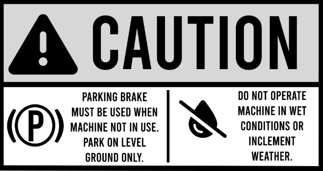
Cautions pose a lesser risk than those of Dangers and Warnings but may result in minor or moderate injury and still need to be accounted for. See Figure 3.
|
Figure 3 |
When parking the Product, the operator must utilize the parking brake to prevent the danger of a roll away incident. This measure also aids in preventing children from tampering with the unit and possibly getting hurt. The Product should only be parked on level ground and pointed in safe directions for if it were to roll.
The Product should not be operated in wet conditions. Wet conditions can increase the risk of losing traction making for unsafe handling of the Product. Operating in wet conditions may result in potential injury to the operator, bystanders, or property. Operating conditions to avoid include rain, dew, snow, sleet, standing water, mud, high moisture presence, and any inclement weather.
Additional Safety Guidelines
The product is not a toy and must be treated with care, common sense, and good judgement by the operator.
Do not drive the Product near open flames, sparks, ignition systems, or sources of heat as it may pose a fire hazard like previously mentioned. This includes but is not limited to running or hot engines, lit cigarettes or cigars, gas or electric heaters, and any other possible source of heat, fire, or spark.
Do not ride, carry passengers, or allow individuals to ride on the Product at any time. This includes using the product to tow people or objects. The Product is designed solely for the purpose of transporting approved substances and should not be used as a mode of transportation for individuals, including children or small passengers.
Do not use the Product as a means of transporting objects. Placing additional items on the Product can adversely affect the weight distribution and center of gravity, potentially compromising stability and increasing the risk of tip-overs or loss of control.
Do not step on the product. The Product is not designed for additional objects, people, or any added weight other than what approved fuels it was designed to carry. There is a “No Step” sticker located on the platform that is underneath the fuel tank. Avoid misusing the product at all cost.
Do not dump, spill, or empty the contents of the tank in any unapproved container, vessel, or location. This may cause a risk of injury or environmental concern.
Operator Requirements
It is important for the operator to be fully capable of operating the machine. There are age, physical, and mental limitations that should be addressed before operating the Product.
User must be 16 years of age to operate. A standard exercised in many states across the country involves restricting anyone under the age of 16 from operating a commercial fuel pump (standard gas station pump). For safest best practice, no person under the age of 16 can operate the Product.
Operator must currently possess the physical capacity, free of injuries, and possess all necessary body parts to safely and effectively control the machine. Operator’s must ensure that they are in good physical condition, without any impairments that could compromise their ability to operate the product safely.
Operator must possess the mental capability necessary for safe and effective control of the product. Users must be free from any mental limitations that could impair their judgment or decision-making while operating the product.
It is the owner and operator's responsibility to assess their own capability, and capability of other operators, before using this product. If there are any concerns about an individual’s physical or mental ability to safely meet these user requirements, it is strongly advised that the user refrains from operating the product.
Operating Conditions
The product is designed to be used in specific environments and those details and product limitations are outlined in this section.
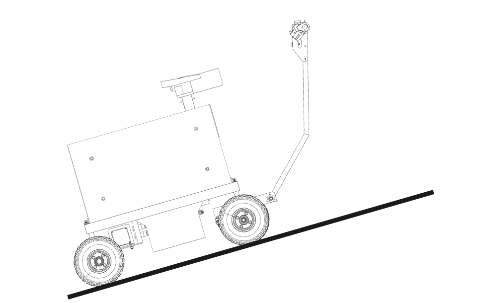
Do not operate the Product on inclines or declines greater than 16 degrees (~28.5% grade) for extended distances regardless of payload or tank content capacity in the front to back plane. This condition is commonly referred to as “pitch”. See Figure 4. Always use two hands and be ready to apply the brakes when operating on any grade/pitch.
Additionally, see the section on Loading Procedure, along with Figures 19, 19a, and 19b, for specific incline limitations when loading your Smart Ass Fuel Mule™ Gas Caddy into a truck or trailer.
|
Figure 4 |
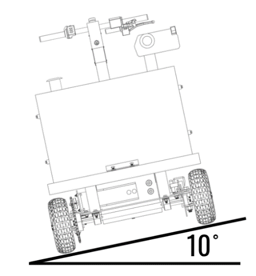
Do not operate the Product on inclines or declines greater than 10 degrees regardless of payload or tank content capacity in the side to side plane. This condition is commonly referred to as “Roll”. The traction surface you are operating on may require roll to be kept at or near zero. You must be able to use your judgement regarding the presence of adequate traction, taking into consideration the surface being operated upon and it’s present condition. Dry, hardpack, stable surfaces are best. Loose rocks, leaves, and other debris are not great traction surfaces. Wet conditions are not advised. Exercise caution and good judgement. See Figure 5.
|
Figure 5 |
Do not use Smart Ass Fuel Mule™ Gas Caddy with Pump in wet conditions. The product is designed to be used in dry conditions only. Excluded operating conditions include inclement weather, rain, dew, wet surfaces, mud, standing water, high moisture, oil or other chemical stained/wet and other potentially slick surfaces. The Product was designed for use in dry conditions where best traction can be attained.
Do not use the Product on loose terrain or poor traction surfaces as it may lead to loss of control or accidents. This includes loose rocks, gravel, leaves, slick surfaces, and more.
Do not operate the Product in temperatures outside of this range of 32°F to 104°F.
Section 3: Product Details
Product Components
The product contains various components with each having their own individual function or contributing function to the overall product making this fuel caddy with pump the ultimate fuel transfer solution available. The operator should recognize these various parts of the product and understand their purpose and how they are utilized.
Transfer Tank : This is the DOT Approved 50-Gallon aluminum transfer tank used to carry and transport approved fuels. It has a DOT certification and to maintain the DOT certification needs to be tested every 2.5 years as stated by the DOT regulations. Refer to your local states guidelines to renew this registration should you need it for your case. For more information on the Transfer Tank’s DOT information and recertification process, please visit the link below https://www.atitank.com/wp-content/uploads/2023/09/2023-Special-Permit.pdf See Figure 6.
Fuel Pump: This is a fuel pump used to transfer the contents of your Gas Caddy with pump into the desired vessel being filled. This fuel pump is powered by the onboard 24V power supply. This pump used is a product of Great Planes Industries (GPI) , website https://greatplainsindustries.com/ , and the user manual for the specific pump is included with the product. If you did not receive this manual or you received an incorrect manual, please contact us at info@smartassproducts.net and we will provide you with the correct user manual for your pump. See Figure 6.
Fuel Nozzle: This auto-stop fuel nozzle controls the flow of the fuel when dispensing fuel out of the Transfer Tank when using the Fuel Pump. See Figure 6.
Steering Arm: The steering arm is used steer the Product and, in some cases, provide backup assistance in the propulsion of the Product. See Figure 6.
Wheels: The wheel assembly, consisting of the tube, tire, multi piece wheel, wheel hub, and wheel hardware, is what allows the Product to roll and become mobile. The wheel specs chosen give the Product the ability to traverse a variety of terrain, including mild off road terrain, with adequate grip. See Figure 6.
Fill Cap: This a two-way vented and removable cap on the Transfer Tank. This cap screws on and off the tank giving you the access port to load fuel into the tank, or in some cases a manual access for removing contents. It has a security hole in the lid that allows for the use of a lock. See Figure 6.
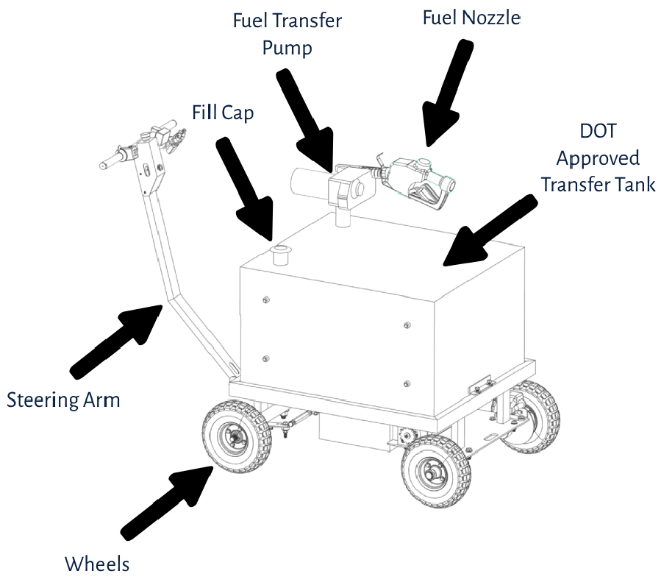
|
Figure 6 |
Hydraulic Hand Brake: This is the lever which is used to stop the product and modulate speed particularly when descending a slope or grade. It utilizes several components such as the brake lever, brake fluid reservoir, brake cylinder, brake line, and brake caliper. See Figure 7.
Brake Fluid Reservoir:This is the reservoir that stores the brake fluid used for braking. The brake fluid reservoir only accepts DOT 3 brake fluid. This reservoir is built into the Hydraulic Hand Brake system. See Figure 4.
Parking Brake Lever:This is the locking lever used to lock the Hydraulic Hand Brake in place when parking the Product to preventing undesired rolling, especially when transporting the unit via a tow vehicle or trailer and when parking the Product. See Figure 7.
Hydraulic Brake Line: The Hydraulic Brake Line is used to connect the hydraulic hand brake to the hydraulic brake caliper via a closed airtight connection to transfer the hydraulic fluid.
Thumb throttle:This is used to control the speed of the Product as well as the direction utilizing the reverse toggle switch. The Thumb Throttle sends a signal to the motor controller to give a desired speed output. The Thumb Throttle also contains a battery indication light that will illuminate with respect to how much battery life remains. Green means mostly full or fully charged. Yellow indicates some battery remains. Red indicates low battery and requires charging. The Thumb Throttle is located on the steering arm on the right side handle. See figure 4.
Electronics Box:This is the electronics enclosure mounted to the steering arm that holds the electronics utilized while operating the Product. See figure 4.
Handle Grips: This is the rubber hand grip that is used to add comfort and grip to users when grabbing, steering, and using the steering arm on the Product. There are two grips on the Product, one on each side of the steering arm. See figure 4.
Emergency Stop:This is the emergency kill switch used to cut all power to the Smart Ass Fuel Mule™ in the case of a potentially dangerous scenario. This cuts power to the entire system including the drivetrain and the fuel pump. The emergency stop is located on the steering arm mounted to the electronics box for easy and quick access. Keep in mind that if cutting power while on an incline, you must be prepared and apply brakes to prevent the Product from rolling down said incline. See figure 4.
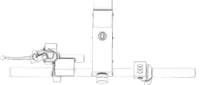
Key Switch:Used to power on the Product and select between powering the drivetrain or powering the fuel pump. This key switch is a 3-position switch with the middle position being off, left position (counter clockwise) being powertrain on, and the right position (clockwise) being fuel pump on. The Key Switch is located on the steering arm mounted to the electronics box. See figure 7.
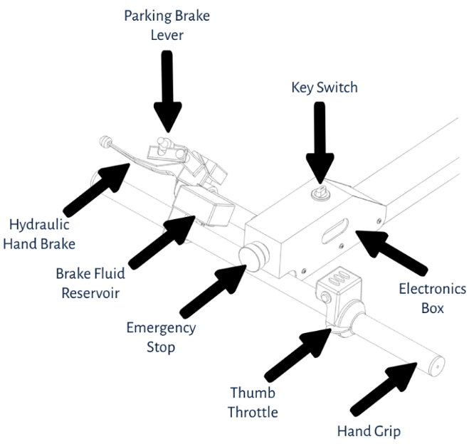
|
Figure 7 |
Chassis:This is the welded steel frame that the tank, powertrain, steering arm, and other components are secured to making up the product. See Figure 8.
Battery Box:This is a removable water resistant enclosure that houses the batteries, relays, motor controller, resettable circuit breakers, charging port and other electronic components. It is located under the Transfer Tank in between the chassis frame rails. See Figure 8.
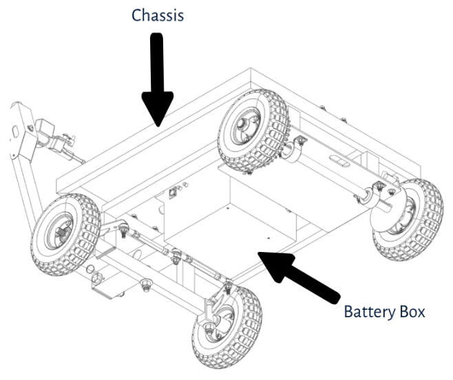
|
Figure 8 |
Hydraulic Brake Caliper: The hydraulic brake caliper is what generates the clamping force due to the hydraulic pressure generated by the hand brake lever. The hydraulic brake caliper clamps the brake disc and modulates the speed of the Product as the operator increases or decreases the clamping force via the hand brake lever. See Figure 9.
Brake Disc: The brake disc is located on the rear axle and is the frictional surface that the brake caliper is clamping to modulate the overall speed of the Product. See Figure 9.
Axle:This is the 1” zinc coated steel shaft that the rear wheels are mounted to. Also mounted on the axle is the Brake Disc, Chain Sprocket, Axle Collar Locks, Locking Collars and Axle Bearings. The axle is mounted to the chassis through the axle bearing. See Figure 9.
Axle Collar Locks: This is a bolt on clamp that locks onto the Axle and creates a backing for the rear wheels be fixed in place. See Figure 9.
Chain Sprockets: The powertrain chain sprockets are used to transfer motor power to the rear wheels. There are two sprockets on the Product, one on the motor (drive sprocket) and one on the rear axle (driven sprocket). The sprockets are for a 420 roller style chain.
Axle Bearing: These mount the axle to the chassis and allow the axle to rotate freely. They are located on the underside of the Product mounted to the motor plate portion of the chassis. See Figure 9.
DC Motor:This is the powertrain motor that is used to propel the Product through the chain drive system connected from the motor to the rear axle. The motor itself is a high power IP65 brushless motor geared for torque through the connected gearbox and chain drive system. See Figure 9.
Wheel Lug Nut: This is used to secure the wheel on to the axle and spindle. There are four total Wheel Lug Nuts, one for each wheel. These lug nuts are intended for a single use and should be replaced if they are removed after having been used. See Figure 9.
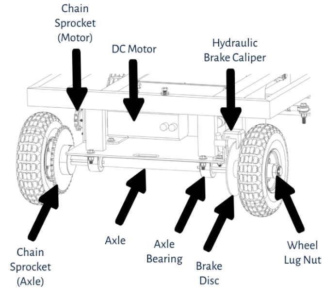
|
Figure 9 |
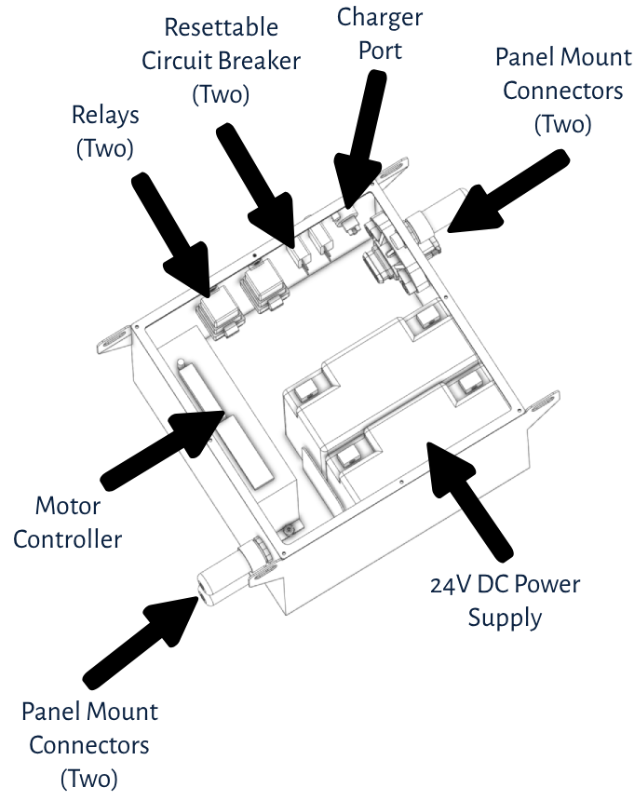
Motor Controller : The Motor controller is used to control the drivetrain motor speed and direction. It receives throttle sensor input, power-on input, and outputs the signal to the motor. See Figure 10.
Batteries:The power supply consists of two 12V lead acid AGM batteries wired in series creating a 24V power supply to power the entire system. See Figure 10.
Relays:The relays control the high current switching between the electronic components on the Product. There is one relay for powering the DC Motor and another for powering the Fuel Pump. These are located inside the Battery Box. See Figure 10.
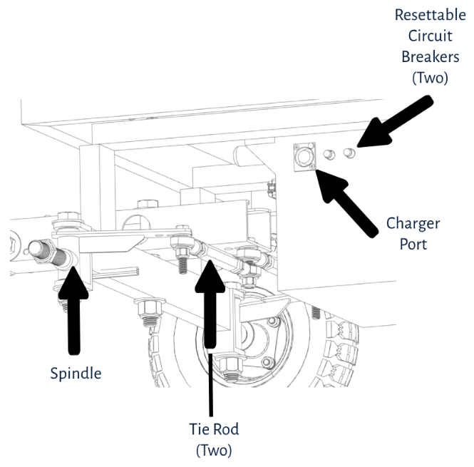
Resettable Circuit Breakers:The Resettable Circuit Breakers are used to prevent component failure in the event of high current draw above normal operating conditions. There are two of these on board, one is for the DC Motor and the other is for the Fuel Pump. See Figure 10 and Figure 11.
Charging port:The Charging Port is used to plug in the battery charger to charge the onboard 24V battery system. The Charging port is located on the side of the Battery Box. See Figure 10 and Figure 11. .
Panel Mount Connectors:These are used to connect the electronic components outside the Battery Box to the inside of the Battery Box where the Motor Controller and other various components are mounted. There are four total Panel Mount Connectors used on the Product. One is for the Fuel Pump, one is for the handle electronics, and the remaining two connectors are for the DC Motor power wires and DC Motor sensor signal wires. These are all located on the Battery Box. See Figure 10
|
Figure 10 |
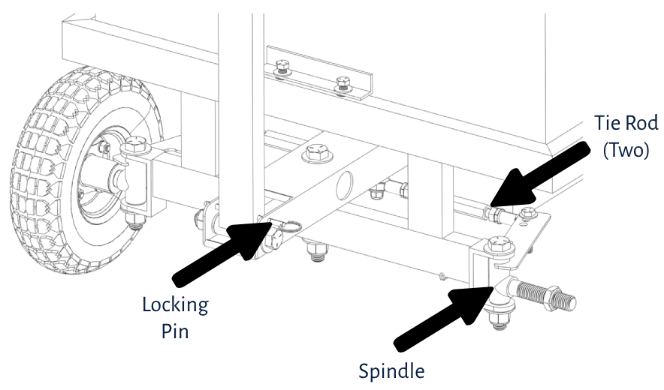
Spindle:This is what the front wheels mount to and are controlled by the steering arm through the tie rod linkage. The Product has two spindles, one for the front left wheel and one for the front right wheel. See Figure 11 and Figure 12.
Tie Rod:This is the adjustable link between the steering arm base and the front wheel spindles to control the steering direction on the front wheels. See Figure 11 and Figure 12.
|
Figure 11 |
Locking Pin: This is used to fix the steering arm position so when the Product is being transported or the arm is not In use. The steering arm is locked in the upright position for storage or non-use and will not fall causing potential damage to nearby objects or people. IMPORTANT! This locking pin is intended to secure the arm when your Smart Ass Fuel Mule™ Gas Caddy is in transit. Never pull on the steering arm without removing this pin, or pin may bend and become difficult to use. See Figure 12.
|
Figure 12 |
Grommets: The grommets prevent any wear or chaffing on the components like the wiring or brake lines that are passing through any metal passageways. There are grommets on the Steering Arm and Steering Arm Base.
Hardware: This includes components such as bolts, nuts, locknuts, washers, lock washers, sleeve bearings, rivet-nuts and more are used to mount components together to assemble the Product. Hardware is used in various places on the product and can be observed in many locations.
Fuel Hose: This allows for fuel to travel between the fuel pump to the fuel nozzle. Built into the UL listed hose is an antistatic wire to equal out the electrical potential between the fuel nozzle and the overall Product since the Product was designed to have the same potential across all parts for safety reasons preventing static discharge.
Axle keyway : The axle keyway is used to lock and sync the rear axle with other rotating components, such as wheels, brake disc, and sprockets. This allows the components to stay in sync with the Axle so that the components all spin together. There are three axle keyways on the Product. One on the motor, one for the right rear wheel and sprocket, and one for the left rear wheel and brake disc.
Air Vent: The Battery Box comes equipped with an air vent to vent any building of gasses, heat, and pressure. This is an IP rated that allows pressure venting but also prevents ingress of water and moisture.
Fuel Compatibility
The Smart Ass Fuel Mule™ Fuel Caddy is designed to work with certain approved fuels. The acceptable fuels are gasoline and gasoline blends (up to E15), Diesel and Biodiesel fuel blends (up to B20), and Kerosene, AVGAS, and Jet A. The Product can hold a volume of 50 Gallons and the gross weight of the Product fully loaded will vary.
· AVGAS can weigh up to 6.02lb per gallon, your Fuel Caddy will weigh approximately 513lbs when full.
· Gasoline can weigh up to 6.3lb per gallon, your Fuel Caddy will weigh approximately 527lbs when full.
· JET A Fuel can weigh up to 6.75lb per gallon, your Fuel Caddy will weigh approximately 550lbs when full.
· Diesel can weigh up to 7.1lb per gallon, your Fuel Caddy will weigh approximately 567lbs when full.
· Kerosene can weigh up to 7.1lb per gallon, your Fuel Caddy will weigh approximately 567lbs when full.
Do not use this Product with any other fluids other than those for which it was designed and approved for. To do so may damage the components and will void the warranty.
Section 4: How To Operate your Smart Ass Fuel Mule™ Gas Caddy with Pump
Driving Procedure
Follow these steps before attempting to drive the product. Following these procedures will help ensure the operator has the best operating experience while ensuring safety to all parties.
1- Inspection
Inspect the Product for any visible damage, wear, or abnormalities. This includes components such as the tires for low pressure or damage/lack of tread, wiring for cuts and abrasions, fuel and brake line components for leaks or bad seals, wheel lug nuts and hardware for loose or unthreaded nuts and bolts, and other visual defects. If a visual abnormality is observed, please refer to the “troubleshooting” or “Repairs” portion of the user manual for assistance.
2- Fuel Check
Perform a visual and ‘smell check’ inspection of the fueling components to see if there are any leaks, fumes, or signs of potential fuel leaks present. This includes fuel odors as well signifying there may be a fuel leak or at a minimum fuel vapors present. Tank, fuel nozzle, fuel swivel, fuel hose, fuel pump, and surrounding areas should be inspected at a minimum. If any of the above present, dry the location accordingly and wait no less than 1 hour to reinspect. Repeat this process until there is no fuel presence then continue on with these steps. Please see the “Troubleshooting” and “Repairs” section of the owner’s manual for assistance.
3- Battery Check
Ensure there is adequate battery life to complete the desired operation. You can reference the charge light indicator on the charger brick. If the light is Green then the Product is considered fully charged. If yellow, the product is adequately charged for a typical use case, though you should consider fully charging the product before heavy usage. If the charge indicator is red, then it is not done charging and it is advised to wait until it is green before operating. For added reassurance of adequate battery life, check for the green light on the thumb throttle to be illuminated after a fresh charge
4- Brake System Check:
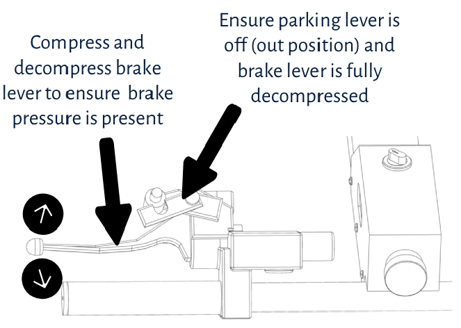
Confirm the brakes have adequate pressure by compressing the lever a few times, feeling for resistance and pressure in the brake system (lever action should be stiff). Release the parking brake ensuring the Product is free to roll. See Figure 13.
|
Figure 13 |
If there is little to no pressure in the brake system, do not operate the product until brake system is corrected and pressure is present. Please refer to the “Troubleshooting” or “Repairs” section of the User Manual to learn how to troubleshoot this issue.
5- Controls Check
Observe the function of the Product’s physical controls by taking the steering arm (while powered off) and turning the arm side to side as well as up and down. Make sure there is free range of motion with no outside or system components causing any interference. If there is an observed controls issue, do not operate the Product until the controls issue is resolved. Please refer to the “Repairs” and “Troubleshooting” section of the User Manual for assistance.
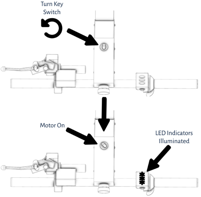
6- System Power
With the previous check complete, ensure the Product is unplugged from the charger and ready to use. Go ahead and power on the key switch by switching into Drive (key switch counterclockwise). Before giving it any throttle, you should see the thumb throttle indicator lights illuminate. See Figure 14.
|
Figure 14 |
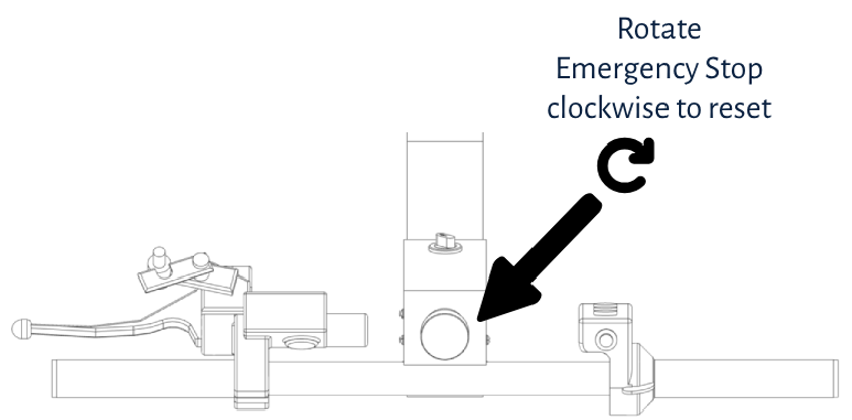
If the LED indicators on the thumb throttle of your Gas Caddy do not illuminate, make sure the estop/emergency stop is reset and not tripped, cutting all power. This can be done by gently rotating the Red Emergency Stop button clockwise until it unlocks, and the button pops out confirming it is reset and not engaged. See Figure 15.
|
Figure 15 |
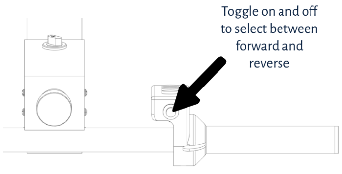
Ensure the desired operation area is free and clear of objects and obstacles to reduce the chances of hitting other objects. With both hands on the handle, one on the thumb throttle and one on the brake lever, go ahead and confirm forward motion and reverse motion by applying a small amount of throttle while staying ready on the brake if needed. Once the first direction is confirmed and working, toggle the reverse switch and apply a small amount of throttle to test reverse. See figure 16.
|
Figure 16 |
Once all drivability functions have been confirmed to function properly and as expected, you are ready to use your Smart Ass Fuel Mule™ Motorized Fuel Caddy! Please ensure you read and follow all guidance and precautions in this manual as you do so!
Smart Ass Fuel Mule™ Gas Caddy with Pump - Loading Procedure
Follow these instructions outlined below for the best and safest operation of your Smart Ass Fuel Mule™ Motorized Gas Caddy with Pump when loading the Product.
1- Loading Area Inspection
When beginning the loading procedure, first inspect the loading area to ensure it is open, free of objects, and conditions are dry with adequate floor/ground traction for the tires to have good and proper grip. Confirm the transportation vehicle that the Product is being loaded into is stationary and in a parked state with all proper parking brakes or parking measures applied.
2- Ramp Setup
If using ramps into a pickup truck, ensure the ramps meet the requirements. Ramps must be a minimum of 1,000lb rated total, which is 500lb per ramp. The operator must also ensure that the operator’s weight added to half the Product weight (full can be up to nearly 570lbs, half of this is 285lbs) does not surpass the weight limit of the ramps. For instance, If the Operator is 250lbs and the half product weight is 285lbs, the 500lb ramp will no longer work. Since the operator will be walking on one ramp while unloading and the total weight on one ramp will be 535Lb, 35lbs over the limit.
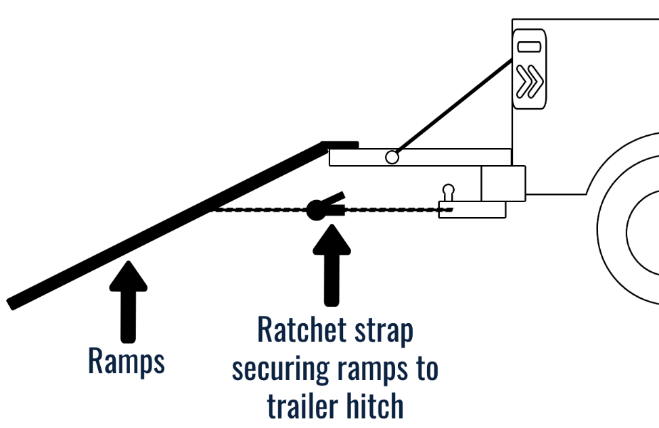
Place the ramps on the truck loading platform according to the ramp manufacturers specs. Additionally, operators should use straps to fasten the ramps to the truck to firmly press the ramps up against the truck platform to prevent movement during operation. See Figure 17.
|
Figure 17 |
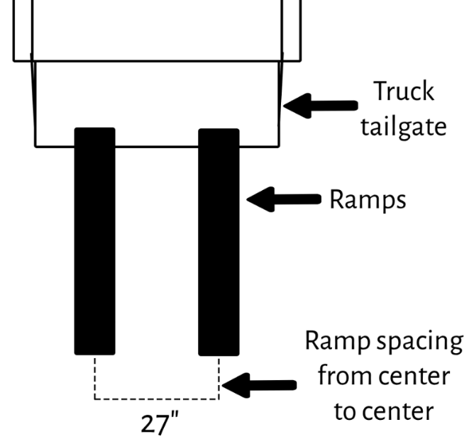
With the ramps strapped down and in place, confirm the wheel spacing is equal to the wheel base of the Fuel Caddy. The width from the center of the left wheel to the center of the right wheel is 27” inches. Using a tape measure, confirm that the ramp spacing is 27” inches center to center of the ramps at both the top and bottom of the ramps. See Figure 18.
|
Figure 18 |
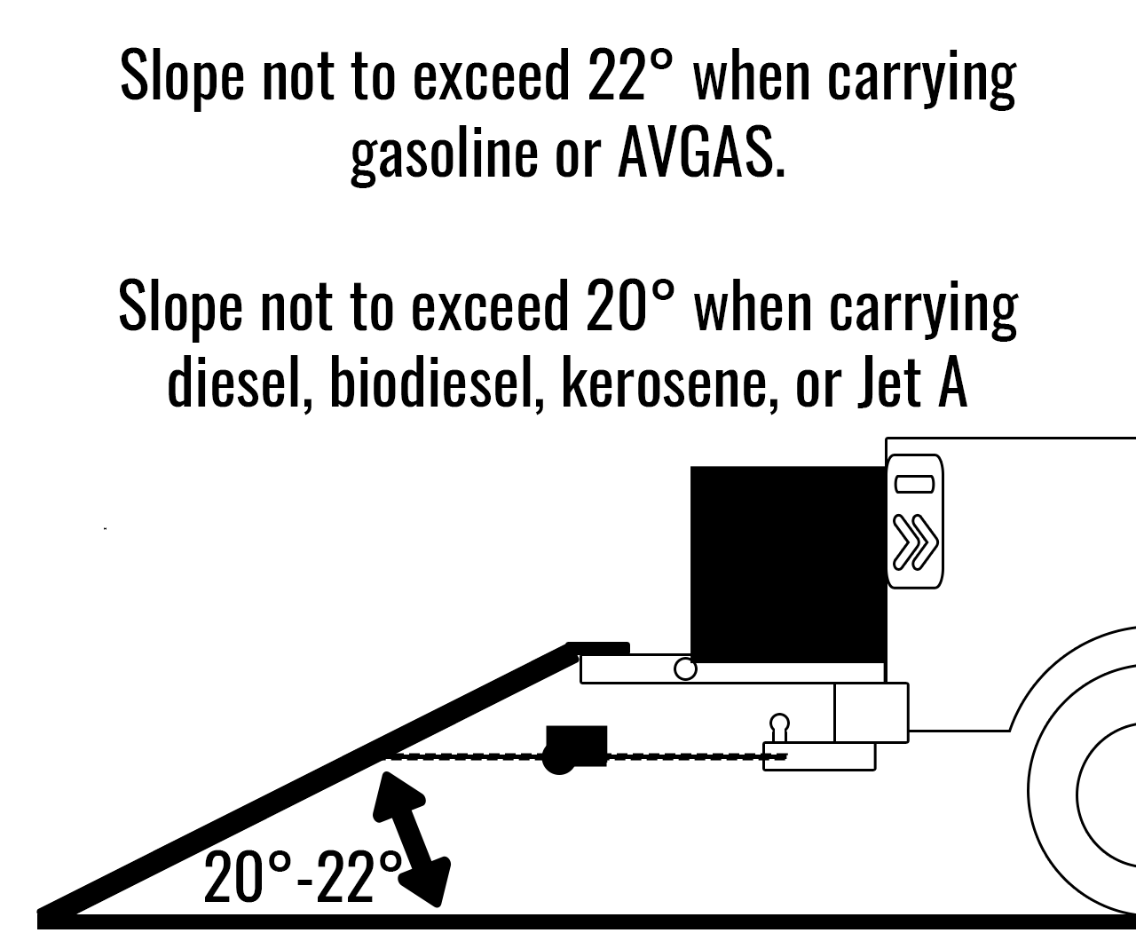
The slope of the ramps when set up on the pickup truck must not exceed 22° when transporting gasoline or AVGAS. This maximum slope angle is 20° with diesel, biodiesel, kerosene, or Jet A due to the increased weight when full. One of many ways you can check what angle you are at is with a simple level finder app for your smartphone. The iPhone App Store has a simple app called ‘Level’.
If the incline of the ramps you are using is greater than the allowable angle, you have two options. See Figure 19 and 19a.
· Use longer ramps to reduce the incline – the longer the ramps, the lower the angle. See Figure 19a.
· Reduce the elevation change between the truck/trailer bed and ground using a hill or high spot. With the truck parked on flat ground, but backed up to a higher spot, perhaps a small hill in the yard, you can use this to reduce the angle of the ramps.
|
Figure 19 |
You can use this chart to determine the length of ramp you will need to achieve an acceptable slope angle for loading/unloading of your Smart Ass Fuel Mule™ Gas Caddy.

|
Figure 19a |
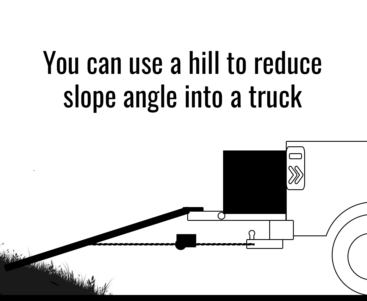
If you have a very tall truck, or your ramps are a little short, you can use a hill to solve your problem in some cases. With the truck on flat ground, and the ramps resting on a higher point due to an available hill you can make use of, you can dramatically decrease the slope of the ramps into your truck.
|
Figure 19b |
3- Controls Test
With the ramps setup and ready for use, confirm the driving functions of your Motorized Fuel Caddy before proceeding. Key on the Product by switching the Key Switch to drive (counterclockwise). Ensure you are heading in the proper direction by checking the reverse toggle button for forward direction (apply brakes, use light throttle to test direction, reverse if necessary). While test driving the Product, ensure there is adequate brake pressure and confirm the Product stops when applying the brakes and that there is adequate pressure. Check that the Emergency Stop works by operating the throttle and testing the Emergency Stop thus stopping the Product from driving. Confirm that the steering is indeed tight and turning the wheels as desired.
4- Product Loading Procedure
With the controls check completed, begin by lining up with Product with the ramps. Confirm there are no bystanders in the backward direction of the product if it were to roll back. This is to avoid any bystander from being impacted or crushed in the instance of a loss of control or roll away. The operator must stay in front of the product and be positioned to walk up the ramps first.
*Never operate the Product while the operator or a bystander are downhill or down ramp of the product as a component failure or misuse of the product may result in a sudden loss of control of the Product. This can lead to the Product rolling down the ramps potentially crushing the operator or bystander.*
With both of the operator’s hands on the handle, one hand controlling the throttle and the other controlling the brake, the operator may begin to slowly walk backwards up the ramps watching their footing the entire way up. The operator should be ready to brake at any moment if need be (always be ready on the brake). Modulating the throttle the whole way up the ramps maintaining a safe speed. Once up the ramps, the operator then uses the brakes to bring the product to a stop in the desired parking location for transporting.
*If at any moment the operator stumbles, loses footing, or misses a step and begins falling, it is advised that the operator let go of the Product and attempt to orient themselves away from the product. This will help to prevent being crushed or pulled and dragged with the Product. Because there are no bystanders in the backwards direction of the Product, the risk of sever injury(such as crushing) due to a falling on ramps should be significantly reduced.*
5- Securing the Product
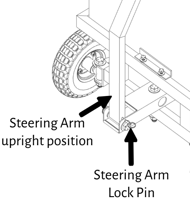
With the parking brake applied and the key switch powered off, the operator can now place the steering arm lock pin to prevent the arm from moving during transportation. This will lock the steering arm vertically. See Figure 20.
|
Figure 20 |
With the parking brake on and the steering arm locking pin set for transport, the ratches straps can now be applied. Strap the product from all four corners of the Product to the transporting vehicle or trailer. There is a tow strap cutout in the rear to secure the product. For strapping in the front, it is advised to strap around the uprights on the front of the Chassis. IMPORTANT! This locking pin is intended to secure the arm when your Smart Ass Fuel Mule™ Gas Caddy is in transit. Never pull on the steering arm without removing this pin, or pin may bend and become difficult to use. See Figure 21.
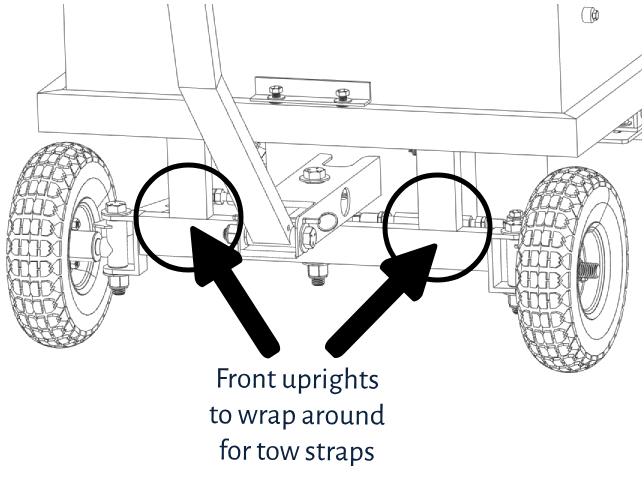
|
Figure 21 |
For strapping down the rear of the Product, it is advised to strap to the existing strap hole provisions cutout in the motor plate. See Figure 22.
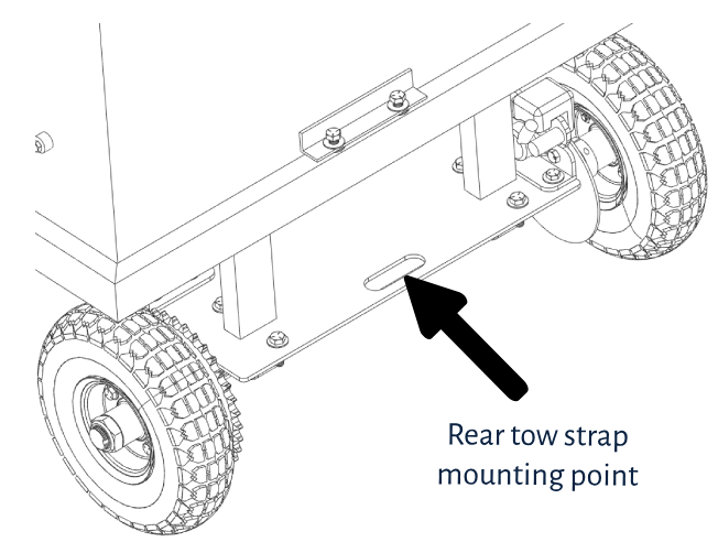
|
Figure 22 |
Smart Ass Fuel Mule™ Gas Caddy with Pump - Unloading Procedure
Follow these instructions outlined below for the safest operation and performance of the Product when unloading. Steps 1 and 2 are the same as steps 1 and 2 of the “Loading Procedure”. Please refer back to the Loading Procedure section above for steps 1 and 2. Once steps 1 and 2 are complete, move on to step 3 below.
3- Unstrapping the Product
With the ramps in place and ready for unloading, the operator can now unstrap the Product. After removing all straps, the operator can remove the Locking Pin and free the Steering Arm for movement and placing the pin in the storage hole on the bottom of the Steering Arm Base.
4- Controls Test
When unloading the Product, it is crucial the controls operate properly. To ensure that the controls work, make sure that the parking brake is off and no longer applied. Begin by applying the brakes and feeling for brake pressure. With adequate brake pressure confirmed, begin turning the steering arm side to side while keeping the product in place to ensure steering is correct and fully functional. With your hand ready to kill the power on the Emergency Stop, key on the powertrain by turning the key switch counter clockwise. Once the powertrain is on, ensure the Product reverse button is toggled. With your hands ready on the brakes, apply a small amount of throttle to ensure the direction is correct and towards the unloading direction and not forward in the direction of the operator.
5- Product Unloading
With the controls check completed, begin by lining up with Product with the ramps making sure to look for both wheels to be lined up to the center of each ramp. Confirm there are no bystanders in the backward direction of the product if it were to roll back. This will avoid any bystander from being impacted or crushed in the instance of a loss of control. It is good practice to have a bystander standing beside the tow vehicle and ramps that is positioned perpendicular to the unloading path. The bystander can help advise the operator if the wheels are indeed lined up with the ramps at all times. The operator must stay uphill of the product and be walking the product down the ramps slowly with their hands on the brakes actively modulating speed the whole time. With the rear wheels on the ramps, gravity begins to pull the Product down the ramps without the need of the throttle. During this time the operator is primarily modulating the brakes, and allowing the product to roll down safely at a very slow speed. The operator should be walking step by step very slowly down one ramp for best handling and footing. Once the rear wheels reach ground level at the bottom of the ramps, the operator may begin to use throttle again to fully drive the Product off the ramps. The operator should continue to watch their footing as they operate the product completely off the ramps onto level ground.
*Never operate the Product while the operator or a bystander are downhill of the product as a component failure or operator misuse may result in a sudden loss of control of the Product and it may begin to roll down the ramps potentially crushing the operator or bystander in the Products path.*
Smart Ass Fuel Mule™ Gas Caddy - Charging procedure
1- Charging Location
Locate an open and well-ventilated area where the Product can be parked on level ground that is dry and out of the weather’s elements. Verify there are no open flames, ignition sources, spark sources, and or heat sources in the area at any time. The location should also have access to a standard 110V wall outlet for power.
2- Setup
Ensure that the Product key switch is off and the Emergency Stop is enabled causing all systems to be powered down. Once power is off, apply the parking brake. Make sure all tank ingress points (fuel fill neck, fuel nozzle spout, and fuel pump bung) are closed and properly sealed. Inspect all fuel components and surrounding areas to verify there are no fuel leaks, fuel puddles, fuel condensation, or fuel vapors present. This includes confirming there is no gas smell present. If any of the above present, dry the location accordingly and wait no less than 1 hour to reinspect. Repeat this process until there is no fuel presence then continue on with these steps.
3- Plugging in to Charge
First start by removing the dust cover on the charging port on your Smart Ass Fuel Mule™ Gas Caddy (on the side of the battery box) and plug the charger in until you hear a click and see that the charger is locked in place. Next ensure that the power cord, this plugs in the brick on one end and into the Product on the other, is firmly plugged into the charging brick. Once confirmed, plug in the charger to a 110V wall outlet. The indication light on the charging brick should light up red indication that the battery is low and that Product is now charging.
4- Charging Duration
The full charge time can be approximately 12 hours depending on how low the battery capacity is upon plug in. It is best to judge accordingly and adjust how many hours you charge based on the presumed battery life left. See Figure 23.
|
Figure 23 |
|
|
Expected Battery Life |
Estimated Charge Time |
|
0% |
11.5 Hours |
|
10% |
10.5 Hours |
|
25% |
9 Hours |
|
50% |
6.7 Hours |
|
75% |
4.4 Hours |
|
90% |
2.9 Hours |
5- Ending the charge
Once the charge duration has been met and the indication light on the charging brick is green, you will repeat the steps performed in “2- Setup” in reference to inspecting the area for any signs of fumes, vapors, and potential flammable substances. This practice is to prevent the ignition of any fuel vapors in the instance the battery charging system arcs upon unplugging. After ensuring the area is free from any potential vapor and fumes and waiting the necessary time if needed, remove the charging connector from the battery box by pushing the tab on top of the connector to release the connector and pull it out from the battery box. From here the Product is now ready to operate.
Smart Ass Fuel Mule™ Gas Caddy - Filling Procedure
For safe and efficient operation when working with any part of the fueling system, it is imperative to adhere to the following safety procedures diligently.
1- Initial Inspection
With the Product powered off, observe any signs of leaks in the fuel system whether it is puddling, dripping, fuel buildup, wet fuel connections, or strong fuel smell indicating a possible fuel leak presence. If any of the above present, dry the location accordingly and wait no less than 1 hour to reinspect. Repeat this process until there is no fuel presence then continue on with these steps. Please refer to the “Troubleshooting” section for assistance.
2- Tank Contents Check
Verify the fuel level and fuel type currently in the Product, this will help ensure the operator of how much of a specific fuel is present and what level of caution to use when filling and dispensing. This will also help avoid cross contamination if the Product is used with more than one fuel.
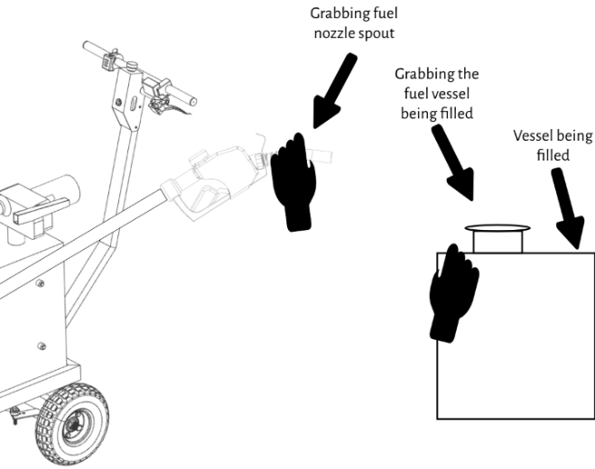
3- Neutralizing Static Electricity Risk
When preparing to fill fuel into the Product, it is critical to handle the different electrical potentials with care. To do this when filling your Smart Ass Fuel Mule™ Gas Caddy with a commercial pump, you will grab the fuel nozzle of the gas station pump that will be dispensing fuel into the product. While grabbing the nozzle and ensuring you are touching metal on the nozzle, you can then use the other free hand to touch the conductive metal away from the fill neck of the Transfer Tank. Grabbing both elements with your bare hands will neutralize the electrical potential between the two systems. Once neutralized, you can now remove the fill cap and insert the nozzle into the Product. From here, the antistatic grounding wire built into the commercial fuel pump will continue neutralizing the potential of the separate systems through the metal nozzle contacting the metal fill neck of the Product. Essentially bonding them together. See figure 24.
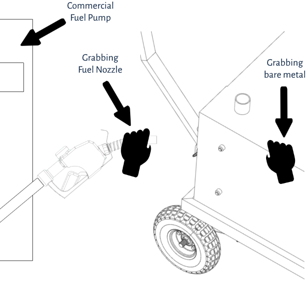
|
Figure 24 |
4- Filling the Product
When ready to fill the product with fuel, there is a necessary airgap to maintain inside your Gas Caddies tank to prevent overfilling. The bottom of the fill neck measures out the maximum level fuel allowed in the product and should never be surpassed. This airgap is necessary for fuel expansion which commonly occurs in hot environments where the tank may begin to build pressure, heat up, and cause fuel expansion or even overflow out of the fuel cap if this airgap is not maintained. Do not fill above this level. See Figure 25.
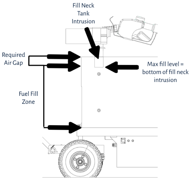
|
Figure 25 |
5- Once Filling is Complete
Once the Product filling is complete, return the commercial pump nozzle to the station, install the fill cap, and ensure the cap is secured and there are no visual leaks present.
Smart Ass Fuel Mule™ Gas Caddy - Fuel Dispensing Procedure
Ensuring safety during fuel dispensing procedures is paramount and must be exercised with caution at all times.
1- Surroundings Check
An inspection of the fueling area must be done before powering on the Product. Check the surroundings for any open flames, spark, heat sources, no lit cigars/cigarettes, or spark potential. If any existing or potential ignition source is observed, do not proceed fueling until the area is free and clear of the potential or existing threats. Ensure that the overall refueling area is clean, dry, and open with good air ventilation. If the area is confirmed to meet these safe conditions, you can position the Product in the desired fueling location and engage the parking brake and key off the power.
2- Initial Inspection
Before attempting to use your Smart Ass Fuel Mule™ Gas Caddy with Pump to dispense fuel, make any necessary repairs to leaks around the seals or connections in the fuel system, hoses, swivels, joints, threads, etc. Make sure the hose is in good condition with no signs of wear or drying/cracking and connections are tight. Ensure the operating area is dry and free from fuel, water, or liquid spills. Confirm that the green grounding wire from the pump to the chassis is intact and is not blemished or damaged in any way.
3- Neutralizing Static Electricity Risk
When preparing to dispense fuel out of the product using the onboard fuel pump, it is important to handle the different electrical potentials with care. Begin by confirming that the key switch is powered off and facing straight. See Figure 26.
|
Figure 26 |
Next remove the fuel nozzle from the holder on the fuel pump. Grab the conductive part of the fuel nozzle, the bare metal portion, and with the other free hand grab the conductive metal portion of the vessel being filled if the product contains a conductive bare metal body or grounded chassis. If the fill vessel does not have a conductive fill neck, grab another bare metal part of the vessel that is grounded. Grabbing both elements with your bare hands will neutralize the electrical potential between the two systems, the Product and the vessel being filled. Once neutralized, you can now insert the nozzle into the fill neck/port of the product being filled. See Figure 27.I
|
Figure 27 |
From here, the antistatic grounding wire built into the fuel nozzle of the Product will continue neutralizing the potential of both systems through the metal nozzle contacting the conductive fill neck of the desired product being filled (if the fill neck is also conductive).
4- Powering the Pump
With the nozzle now in the vessel being filled, ensure that the nozzle is closed and not open for dispensing. Once confirmed, go to the Steering Arm and power on the pump by switching the key switch to the clockwise position. With the Fuel Pump now receiving power, go to the fuel pump itself and lift up the lever which powers on the pump. The lever is located under the nozzle holder and when powered on will be covering the opening that the nozzle is stored.
5- Dispensing Fuel
With the fuel pump now pressurizing the fuel line, you can now press on the fuel nozzle lever dispensing fuel into the approved container or vessel. You may use the auto nozzle feature and allow for automatic nozzle shutoff. While the fuel is dispensing, stand with the Product with your hands ready to kill the emergency stop in the event of any failure, fire, or hazard that arises.
Stay close to the fuel nozzle as well in the unlikely case that the auto shutoff feature fails, you can quickly shut off the nozzle manually. The fuel dispensing of the fuel pump can take anywhere from 3 to 5 minutes depending on how full the tank on your fuel caddy is and the batteries state of charge.
6- Shutting off the Fuel Pump
When you are ready to stop dispensing fuel, ensure that the fuel nozzle lever is now off and is no longer dispensing fuel. Next shut off the fuel pump using the switch on the fuel pump itself. Switching the lever down to the off position will open up the holder location for the fuel nozzle to be stored again. Next go to the Steering Arm and switch the key switch into the off position to reassure all power to the fuel pump is off. With the fuel pump now fully powered off, let the last few drops fall into the vessel, it can help to jiggle it a bit as you remove the nozzle to eliminate any drips. Place the fuel nozzle back in the holder located on the fuel pump. This concludes all the fuel dispensing steps and you may now drive/return the Product to a safe storage location.
Smart Ass Fuel Mule™ Gas Caddy - Driving Best Practices
Before driving the Product, it is crucial for the operator to understand the best practices to ensure utmost safety and performance.
Operators and bystanders should always position themselves uphill from the Product during operation, whether driving the product uphill or downhill. This precautionary measure reduces the risk of potential accidents, ensuring that in the event of a loss of control or if the Product begins to roll, individuals are positioned in a safe location to avoid being run over or crushed by the Product. See Figures 28 and 29.
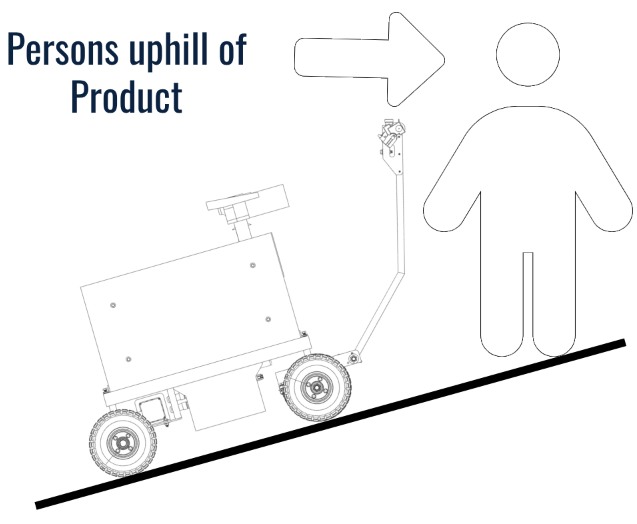
|
Figure 28 |
When navigating the Product downhill, it is advised to operate the Product in reverse with the steering arm and operator positioned uphill of the product. This positioning enables the operator to maintain better control and modulation of speed (via the brake lever) using both hands while ensuring that no user or operator is in the path of the product should the operator stumble or lose control and the Product begin to roll. See Figure 29.
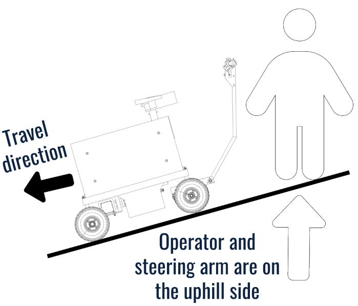
|
Figure 29 |
When traveling uphill, it is advised to also operate the Product from the uphill side. When traveling both uphill and downhill, it is advised that the operator is uphill of the Product and the Product is orientated with the steering arm on the uphill side. See Figure 30.
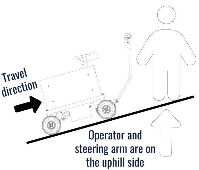
|
Figure 30 |
Do not exceed the slope limitations specified for the Product, these limits can be found in the “Operating Conditions” section. Operating the Product on excessively steep inclines or declines can compromise stability, traction, and control increasing the risk of accidents, tip-overs, or loss of control.
Do not operate the Product on surfaces or structures incapable of supporting the weight of the Product. This includes lighter duty truck tailgates that may not be rated for 600lbs. Your Smart Ass Fuel Mule™ Fuel Caddy with Pump can see weights close to 600Lbs total depending on the fuel used and capacity of the tank. For more detailed product weight specifications, see the “Fuel Compatibility Statement” section of this user manual.
Do not approach fore/aft inclines (pitch) at a side to side (roll) angle. Inclines are to be driven head on for optimal performance and reduced risk of tipping hazards. By head on, this refers to the only direction of incline or decline being in the “Pitch” condition, as mentioned in “Operating Conditions” section.
Do not attempt to modify or tamper with any of the product components, as it may void the warranty and compromise safety.
Do not operate the Product under the influence of alcohol, drugs, or medication that may lead to impaired judgment and or reaction time.
Maintain a safe distance from edges, ledges, or structures that may pose a risk of tipping or falling during operation. Modulate throttle, always ready on the brakes and aware of the E-Stop, if you’re near any sort of obstacle or ledge. In short, don’t be a dumb donkey and run your Smart Ass Fuel Mule™ off of anything. Be a Smart Ass!
If operating the product through rough terrain (specifically climbing inclines) and you experience symptoms such as a decrease in speed, audible electronic whining, or the product not moving as expected, it is essential to take immediate action. Stop operating the Product immediately, apply the hand brake, and reassess the terrain you are traversing. These signs may indicate that you are pushing the unit beyond its designed capabilities. In such instances, the Product’s internal override power cut mechanism may engage. To prevent damage to the motor, the motor controller is programmed to cut power to the motor when overdrawn, to prevent damage to the electronics. This power cut safety feature is a safety feature, but without proper usage, can be potentially dangerous if the operator is not aware or expecting it. So be aware. Continuing to operate the Product under these conditions may compromise its performance, durability, and safety of the Product, of the Operator, and of other persons or property. Therefore, operate with caution and adjust your chosen path to ensure safe and optimal operation of the Product that are within its limitations.
Please adhere to all federal, state, and local laws and regulations/guidelines regarding the operation of the Product. Ensure that you are operating the Product in areas where its use is permitted and in compliance with applicable laws and regulations. Failure to do so may result in violation of laws, regulations, or guidelines and result in legal consequences, fines, penalties or more. It is the operator’s responsibility to ensure adherence to all applicable laws and regulations.
Smart Ass Fuel Mule™ Gas Caddy - Fueling Best Practices
When operating the fueling systems of the Product, it is imperative to follow these best practices to maintain utmost safety and performance.
Use only approved fuels. To see a list of approved fuels for transport, please refer to the “Fuel Compatibility Statement” section of the user manual.
Do not operate any Product near open flames, sparks, ignition systems, or sources of heat as it may pose a fire hazard. This includes but is not limited to running or hot engines, lit cigarettes or cigars, and gas or electric heaters, spark or ignition sources, and other like environments or surroundings.
Do not overfill the Product beyond its suggested 50 gallon capacity. This will affect the weight and performance of the Products driving ability. The possibility of fuel overflow due to temperature based expansion of the fuel may also occur. Failure to follow this guideline may lead to increased risk of injury or property damage.
The operator should ensure all bystanders keep a safe distance away from the Product during the fueling processes. This is especially true for children and those who may be sensitive to the potential fuel vapors of the fuel being transported.
Do not operate the Product in crowded areas. This helps ensure risk of crushing or fuel related injuries are eliminated.
Do not store fuels in the Product for prolonged periods of time. Depending on the type of fuel used and environmental conditions, the quality of the fuel may diminish over time as well as a higher chance of fuel vapor accumulation in the storage location. Extended storage of fuel can lead to issues such as fuel degradation, contamination, or evaporation, which may affect engine performance and reliability.
Always ensure the fueling area is dry, free of objects and debris.
Do not attempt to move the Product while fueling or at any step in the fueling processes.
Smart Ass Fuel Mule™ Gas Caddy - Charging Best Practices
Do not use any other charger with the Product except the one that is provided. The included charger is designed with specific properties to charge the Product in a safe manner. This charger is UL listed as well for assurance of safe charging.
For longevity of the battery, it is advised to recharge the Product after every use for the times referenced in the table on Figure 23. Lead Acid AGM batteries like being in a high capacity state when being stored. Storing the Product with a lower battery capacity will negatively affect the batteries’ lifespan.
Do not power on the Product while the Product is charging. Ensure the Product is unplugged before attempting to move or power on the Product.
Smart Ass Fuel Mule™ Gas Caddy - Loading & Unloading Best Practices
The Product was designed to be loaded into and out of a transportation vehicle, whether the bed of a pickup truck, box or flatbed truck, or trailer. Utilize these best practices for safe and efficient operation.
Use ramps that are rated to support the full weight of the Product and the operator. For more details on this, refer back to the section “Loading Procedure” section of this user manual.
The operator is responsible for confirming the ramps traction potential and incline before loading and unloading the Product. If the slope is greater, longer ramps may be needed and a better loading and unloading location with less of an incline is needed. Longer ramps will reduce the slope, as will creatively selecting a loading location using a higher point on the ground, a small hill for example, to reduce the ramp incline. Back the truck near the hill, truck still on flat ground, such that the end of the ramps will be resting at an elevation higher than the truck tires. This will reduce ramp incline.
Smart Ass Fuel Mule™ Gas Caddy - Storing Conditions
The Product should be stored with care in safe locations that meet the requirements outlined in this section.
Do not store in poorly vented areas. To prevent the presence of fuel vapor build up, only store the product in well-ventilated and preferably outdoor conditions.
Do not store in locations where it may have exposure to open flames, spark sources, ignition sources, heaters, or running vehicles.
Do not store the product where it can have direct or indirect exposure to weather and its elements such as direct sun, rain, hail, and other inclement weather.
For maximum longevity of the batteries, it is best to avoid storing the Product in temperatures outside the range of 32°F to 75°F.
Ensure that the storage location is secure and inaccessible to unauthorized individuals, especially children.
If storing the Product for a long period of time, ensure that the approved substance in the container has adequate properties to be stored for the intended duration to avoid negatively affecting the fuel.
Avoid storing in areas with high humidity or moisture levels as this can potentially lead to corrosion and damage to components on the Product.
Emergency Procedures
This section of the user manual helps train you to react to specific events. Knowing what to do in the instance of a dangerous situation or emergency is crucial for safety of the operator or bystanders.
If a Fire Starts When Fueling.
If a fire starts when fueling, it is key to get persons in the area to safety as quickly as possible. From the “Fuel Filling Procedure”, you as the operator should be positioned ready to hit the Emergency Stop at any moment. At the first sign of danger or a fire, if safely possible, immediately hit the emergency stop. If this is not possible to do in a safe manner, immediately step back away from the unit as quickly as possible and find a safe location a safe distance away, this could be 50’ or more away. Do not attempt to shutoff or remove the nozzle anything else as this will increase your potential risk of injury staying close to the danger. Once you are away in a safe location, notify the local police by dialing 911 and reporting the incident. From there you should take the direction of the authorities.
Loss of Footing While Operating on Ramps.
If you are operating the Product on ramps and you lose your footing causing you to stumble or fall, it is best to ensure your safety and let go of the handlebar and attempt to fall out of the path and direction of the Product. As outlined in this user manual, the operator or any bystanders should NEVER be in the downhill path of the machine meaning the short rolling distance the Product may travel to will be free of any bystanders or operators keeping all person(s) safe from crushing or impact hazards.
Operating on an incline and the Product begins tipping over.
The Product is designed to handle a limited amount of incline and when users exceed these limitations on the product or operate on a loose surface limiting traction, they risk putting themselves or others at risk. In this instance a tipping event can occur. If the Operator exceeds the product limits and the Product begins to tip, it is not advised to try to muscle the handlebar and lower the machine. Rather the operator is advised to let go of the handlebar and relocate themself to a safe direction out of the tipping direction.
The product falls into a body of water with contents still in the tank
First off-- this has never happened. However, if during operation the Product enters or falls into a body of water, the operator should prioritize their own safety. They should attempt to safely position themselves out of the path of falling or danger if they notice the Product falling towards the body of water. Once safely positioned on the dock, if possible, the operator should activate the emergency stop to prevent any power to the systems onboard the Product. If the Product is carrying any fuel, the operator should take immediate action to prevent any fuel from spilling into the water. This may involve ensuring the fill cap is still screwed on tight and the fuel nozzle is closed and not dispensing fuel. Additionally, if fuel absorbent materials are available to contain the spill, this can also be utilized. Contact the local emergency services, such as the fire department or coast guard, to report the incident and request assistance. Provide them with any details about the location of the incident and any potential environmental hazard such as fuel spillage and flammable content presence. Once authorities are notified, retrieving the Smart Ass Fuel Mule™ is the next task. Observing the depth of the water and accessibility of the Product, this may constitute the methods used to retrieve it such as special equipment, recovery services, or calling professionals.
Fuel Spill
In the instance that a fuel spill occurs, it is advised to take action immediately. If fuel has spilled, immediately ensure all power to the Product is killed, using both the key switch and Emergency Stop. Ensure there are no immediate fire threats such as open flame, spark sources, ignition sources, or heat sources that could potentially ignite the spilled fuel and or vapors. Next, take all necessary steps that are both reasonable and safe to stop the continuation of spilling. This could be tightening the fuel cap, shutting off the fuel nozzle, or attempting to right the Product if it has tipped.
Wait at least 1 hour after any fuel spill and after ensuring product is dry and clear of any fuel remaining on the product before powering on the Product and operating it again. This practice prevents any possible ignition sources from being present while fuel spill and vapors are present.
Once the spilling has been reasonably contained depending on the state you are in, it is required to report the fuel spill if it exceeds your states reporting amount. Please confirm with your state’s local guidelines and regulations for the minimum fuel spill that requires reporting. Following your states guidelines, make the report and proceed with the appropriate clean up measures that are both reasonable and safe. The measures also may be recommended or guided by local authorities and it is best to confirm with them on what they advise for the scenario at hand.
Operating the Product on excess inclines straining the components and power cutoff occurs
If you hear the components making a whining or screeching sound, this means you are overpowering the system and it cannot handle the load. This indicates you are carrying either too much weight, or carrying it at too much incline. After two seconds of hearing this sound when driving the machine, the safety power cut off will be engaged in the motor controller to prevent damage of the components. To avoid the power cutting in an unsafe location, immediately let off the throttle while simultaneously engaging the hand brakes when you first hear this sound. Slowly back off the incline or maneuver the Product off the incline as this is exceeding the limits of the Products capability. Once in a safe location, choose a safer option with less incline within the Products limits to proceed. If continuing to operate the machine in the overstrained state and the power cuts, the first response is to fully engage the hand brake and stop the Product from moving. If you are unable to do so and the product begins rolling, it is advised to let go of the handlebar and locate yourself into a safe location out of the path or direction of the Product. The Product can be assessed after it comes to a stop and is off the incline.
Section 5: Troubleshooting
See the chart below to best address and troubleshoot any possible issues you may have with the product involving the driving components or the fueling components. For any fueling component issues not covered here, please refer to the provided user manual for the fuel pump used on your Smart Ass Fuel Mule™ Gas Caddy with Pump.
|
Troubleshooting |
||
|
Symptom |
Possible Issue |
Corrective Measure |
|
A) Key on drive motor and indication lights do not turn on. |
1) Emergency Stop is engaged |
1) Confirm the emergency stop is disengaged and retracted to its outer position. If it is latched, gently twist it clockwise until it releases and resets. |
|
B) Key on drive motor, indication lights turn on, applying throttle and drive noise is present but the Product does not move. |
1) Parking Brake is on |
1) Disengage the parking brake allowing the drive Product to move freely. |
|
C) Key on drive motor, indication lights turn on, applying throttle no noise is present and the Product does not move. |
1) Motor is unplugged |
1) On the back of the battery box are two cylindrical shaped connectors from the motor. Confirm these are plugged in fully and have not become loose. |
|
D) Key on drive motor, Product moves in one direction, reverse switch is toggled and the Product does not change direction when throttle is re applied. |
1) Toggle Switch not fully engaged |
1) Toggle the reverse switch on and off again firmly confirming it latched. Wait a few seconds and then try to apply throttle. If still no reverse function, proceed to next "Possible Issue". |
|
E) Key on to fuel pump, latching on the fuel pumps switch on the pump itself and it does not power on. |
1) Circuit breaker tripped |
1) On the side of the battery box are two resettable circuit breakers. Verify that the red one, this is for the pump, is not popped, as indicated by the button sticking out significantly. If it is, push it in to reset the breaker and try powering on the pump again. If the breaker just popped, you may have to wait a couple of minutes for it to reset internally before you can push the button to reset the breaker. |
|
F) Steering the Product and the wheels do not change direction with the handle. |
1) Tie rods |
1) Check the tie rod links for proper connection. Confirm both ends are secured by the appropriate bolt and nut fasteners. Confirm that the tie rod lock nuts that adjust the tires toe-alignment are tight not allowing for play. |
|
G) No power to the pump or the motor when using the key switch. |
1) Battery is dead |
1) Plug in the charger according to charging directions in the user manual. Confirm the battery is charged according to the charging directions in the user manual. If the charge indicator never turns green and or the machine does not power on after charging the battery, the batteries may be malfunctioning and need to be replaced. Continue to the next steps before confirming the batteries are malfunctioning. |
|
H) Applying the brake lever and there is no pressure. |
1) Low Fluid |
1) Using the glass level indicator in the brake fluid reservoir, confirm if there is adequate brake fluid visible in the reservoir. If there is not, top of the fluid in the reservoir with DOT 3 brake fluid. |
|
I) Applying the brakes, observing brake pressure is present, but the Product is struggling to slow down. |
1) Air pocket |
1) There is a chance an air pocket is present in the brake system. Follow the instructions for bleeding the brakes outlined in the "Repairs" section of the user manual. 3) Observe the brake disc for any signs of brake disc wear such as deep grooves on the disc's surface, a noticeable lip on the edge of the disc, cracks, splits, or other structural problems, uneven wear in the disc, warped disc, excessive noise or vibration during braking, and or decreased stopping power or ability. With any of these symptoms noticed, replacing the brake disc is advised. |
You may also find helpful information in our FAQ (frequently asked questions)!
Section 6: Repairs
If repairs are needed beyond that which is covered in the above troubleshooting section, please contact Smart Ass Customer Service and we will provide guidance on next steps.
Section 7: Maintenance
Maintaining your Product properly is paramount for keeping high level safety, performance, and longevity. There are several components on the Product that should be maintained and routinely checked for wear and functionality.
Batteries
The Product utilizes two 12V VRLA AGM batteries in series to create the 24V system. This battery style is designed for 100 – 300 cycles with a life expectancy of 3-5 years. To maintain the best performance of your Products battery system, charging the battery according to the “Charging Procedure” in this user manual is a big contributing factor. Refrain from deep cycling the battery and constantly running them to a low capacity as this will shorten the batteries lifespan. Avoid storing the batteries below 90% capacity. It is recommended by the battery manufacturer that the operation environment for longevity of the batteries is between 20°C and 30°C (68°F to 86°F). Batteries should be replaced every 3 years or upon notice of failure, reduced battery life, reduced power output, or any additional signs of battery wear impacting the performance. Not proactively replacing the batteries may cause an increased risk of failure during operation which depending on the operation environment and conditions, could result in a major injury or even death.
Tires and Tubes
The wheels and tires, like a standard automotive vehicle, experience wear and tear and need to be observed on a regular basis. The wheels on this product contain a tire and a tire tube that need to be monitored. Firstly, standard operating pressure for the tires on this Product is 30psi. These pressures should be observed before every use to ensure optimal traction and even tire wear.
Next, tire tread. These tires come with tire tread that is semi-aggressive for hybrid concrete and off road use. The tread depth should not fall below 1/8 th of an inch. Anything below this level increases the safety hazard as reduced traction becomes present. This measure can be taken with a standard tread depth tool from a local auto parts store.
The tire tubes are airtight tubes that are inserted between the rim and tire that hold the tires pressure. If the tire itself is punctured, that does not always mean the tire tube was damaged and visa versa. The tire tube may be damaged even if there is no visible damage to the tire. That being said, the only way to judge functionality of the tire tube is by measuring pressure. If you measure the tire pressures weekly and notice a pressure drop at all, this may be a sign that the tire tube is bad or has a leak of some sort. If this is observed, it is advised to replace the tire tube.
Chain
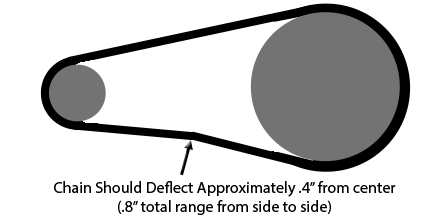
The Smart Ass Fuel Mule™ Gas Caddy is propelled by a chain drive system. This is located underneath the Product near the rear wheel. The chain should have a certain amount of slack to allow for proper motion and functionality. The chain tension should be observed monthly to notice for signs of slack or stretching. If the chain is too tight can cause component damage and excess wear and grinding. If the chain is too loose may derail and come off.
The chain must be tensioned with the proper amount of slack. See the diagram below illustrating approximately .4” of slack from center, .8” total. If the chain is observed to have too much or too little tension, it should be adjusted.
IMPORTANT: Before ever touching the chain or sprocket components, ensure both the key switch is off and the Emergency Stop is activated cutting all possible power to the motor. To adjust the tension, loosen the 4x bolts and nuts that are mounting the motor mount plate to the frame. This will allow for linear motion to slide the motor forward and backward to loosen or tighten the chain. Once the optimal tension is found, secure the hardware to lock the motor mount plate back in place.
|
Figure 30 |
Chain lubrication is also important for longevity. Be sure to lube the chain at least quarterly, or monthly with heavy use. Use roller chain lubricant commonly found at most bicycle or automotive shops. Chain lubrication is especially important if the chain is dry or gets very dirty with dust, mud, and other elements.
Brake fluid
The braking system is a hydraulic disc brake system that uses DOT 3 brake fluid. The fluid reservoir is located on the steering handle built into the steering lever. There is a level indicator glass to check for the level and clarity of the brake fluid. Like automobiles, the brake fluid should be changed periodically. If the brake fluid is low and the fluid is still clear and clean, free of particles, debris, and coloration, you may top it off using approved DOT 3 brake fluid only.
If your brake fluid is observed to be dirty or colored, as in a yellow or brown/black tint to it, it is advised to flush the brake fluid entirely. To do this, please refer to “Repairs” section of this user manual.
Brake fluid is also susceptible to aging and needs to be routinely flushed every 2 years. Replace the brake fluid by doing a complete flush every 2 years to prevent failure and risk of compromised or weakened braking.
Brake Pads
Brake pads will wear with use and will show signs when the pads begin to wear out to the point of replacement. Brake pads will often times start to make a noise during braking signifying wear and need for replacement. If the brake pads start making a screeching noise during braking, they should be replaced. If the brake lever pressure has not changed but the product’s ability to stop feels weaker than it used to be, the brake pads should be inspected and replaced if found to be the root cause. If the brake bad thickness is at or below 1/16”, the pads should be replaced. Operators should verify there is ample brake pad available before every use by looking at brake pad through the gap in the caliper where brake pad thickness is visible. To see how to replace the brake pads, refer to the ”Repairs” section of this user manual.
Brake Disc
The brake discs can also wear and need replacement similar to that of the brake pads. It is important to look for any signs of brake disc wear such as deep grooves on the disc's surface, a noticeable lip on the edge of the disc, cracks, splits, or other structural problems, uneven wear in the disc, warped disc, excessive noise or vibration during braking, and/or decreased stopping power or ability. With any of these symptoms noticed, it is recommended to replace the brake disc. To see how to replace the brake disc, refer to the ”Repairs” section of this user manual.
Section 8: Warranty
Warranty Terms:
Your Smart Ass Fuel Mule™ gas caddy with pump is built to last, and guaranteed! The warranty period begins on the day the unit is purchased and confirmed with the original purchase receipt. If proof of Purchase date is not available, the date of manufacture is used. Smart Ass Products, LLC hereby warrants that any new Smart Ass Fuel Mule™ purchased from Smart Ass Products, LLC or any Authorized Dealer within the United States, will be free from defects in material and workmanship for predetermined times and subject to the limitations stated in this warranty document.
Warranty Exclusions:
Warranty shall not apply if the product has been subject to abuse, misuse, neglect, negligence, accidental damage, and or has not been operated in accordance with manufacturer’s operating instructions. Additionally, any attempts to alter, modify, or adjust any aspect of the unit outside the warrantor’s duly appointed representative also voids the warranty. Warranty shall not apply to wear and tear item. Smart Ass Products, LLC is not liable for incidental, consequential or special damages.
Warranty Resolution:
All warranty claims should be sent directly to info@smartassproducts.net with the subject line listed as "WARRANTY CLAIM". If a warranty claim has been approved by Smart Ass Products, LLC, the item(s) may be returned to the factory to be repaired or replaced free of charge. Smart Ass Products, LLC will cover the shipping cost of the replacement item(s) to the customer however, the customer is responsible for shipment of product(s) to the factory. If a customer chooses to drop off the warrantied item(s), there is no charge for repairs or services rendered. Drop off is at the Smart Ass Products, LLC Headquarters in Gainesville, GA. Please refer to your RMA contact to schedule your drop off.
If an authorized Smart Ass Products, LLC dealer is local to the customer, an arrangement will be made by Smart Ass Products, LLC to have the warranty work completed at the specified dealer location. If this is not the case, the primary option stands with Smart Ass Products, LLC being the only authorized warranty servicing location.
2- Year Warrantied Parts
GPI Fuel Pump M240S1- Year Warrantied Parts:
- Frame
- Fuel Tank
- Fuel Nozzle
- Fuel Line
- Fuel Fittings
- Batteries
- Drive Motor
- Axles
- Spindles
- Motor Controller
- Throttle
- Key Switch
- Emergency Stop
- Electronic Components
- Charger
- Relays
- Connectors
- Circuit breakers
- Plugs
- Wiring Harness
Parts Excluded from Warranty (wear items):
- Tires
- Tubes
- Brake Pads
- Brake Fluid
- Chain
- Sprockets
- Bearings